When connecting multiple batteries together to create a larger battery bank, it is important to configure the bank so all batteries are charged and discharged as equally as possible. This makes the connection method and interconnection between batteries a critical factor to ensure batteries receive equal charge and are discharged at the same rate as the others in the bank. Harder working batteries will typically fail earlier than the other batteries in your bank, and, in some cases, cause problems with the entire battery bank. The main cause for this issue is a small amount of resistance between battery connections and the solution is proper balancing. “Balanced Charging” eliminates the problem by evenly distributing the resistance between the connections across each battery, and ensures similar, full lifespans for all the batteries in the bank. In addition to the need for consistent interconnecting leads for each battery, the length and size (i.e. wire gauge) of the battery leads should also be consistent to achieve Perfectly Balanced Charging. Windy Nation recommends using a minimum of 2/0 AWG cables to interconnect batteries, and that gauge of wire should remain the same throughout the entire system to maintain the same resistance level.
Charging Batteries in Parallel
When charging batteries in parallel it is common to have batteries fail sooner than anticipated. This is largely in part because the batteries are simply connected as instructed: positive to positive and negative to negative. While from an electrical perspective, this is correct, when more than two batteries are in parallel, adding the third and fourth batteries in a linear fashion as shown in Figure 1, will cause drastic imbalanced charging.

Unbalanced Charging: Effects of Resistance
In typical installations, the batteries are connected side-by-side (negative to negative, and positive to positive), starting with the first battery connected to the second, and so on until connecting to your charge controller; see Figure 1. Theoretically, each battery is receiving the same amount of current when charging, however, small yet measurable amounts of resistance exist between each battery connection making this not the case. The reality is that the battery connected directly to the charge controller will draw more amperage (charge) than the battery furthest down the bank, as the current is reduced through each interconnection due to this resistance. This difference in current between the closest and furthest batteries from your charger can be very significant and in some instances up to twice the amount of current drawn by the closest battery, see Figure 2.
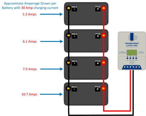
Figure 2 for Unbalanced Charging demonstrates the charge effect using a 30A charger, where the first battery will inevitably be worked harder and charged faster than the next one downstream, with similar results for each battery all the way down the string. Note the drastic amperage decrease between the first battery and the last battery in the system, with a 50% difference between the first battery and the last battery. The above effect becomes more drastic as additional batteries are added to the system and assumes, proper cable sizing as well as the same type, age, and size of batteries are in use. If for example, this was a deep cycle battery connected to a starting battery, or two old batteries with two new batteries, or even a group 24 with a group 31 sized battery, the effect will be even more pronounced. Unfortunately, this configuration represents how most battery banks are configured and just to be very clear, this is NOT proper and represents an unbalanced system. Batteries paralleled together in this formation will result in premature failure and shortened lifespans, due to the uneven resistance levels. “Balanced Charging” is a way of eliminating this problem by evenly distributing the resistance between the connections across all the batteries, ensuring that they all have a similar, full lifespan.
Balanced Charging
The easiest method to achieve better ‘Balanced Charging’ is to rewire one set of leads (positive or negative) so it is connected to the opposite end of the battery bank; see Figure 3.

Wired in this fashion, each battery will draw current through exactly three interconnecting leads. However, while this method of wiring is much better, it is still not perfectly balanced since the outermost leads will draw slightly more total current than others, and therefore will experience drops in voltage along their length. This “Better” wiring method may be suitable for many applications, where space may be a concern or the additional wiring is not possible, and provides no more than a 15% difference between the primary contact battery and the secondary battery. This method of balanced charging can also be used effectively with both even and odd numbered strings, but there is a way to achieve Perfectly Balanced Charging
Perfectly Balanced Charging
Figure 4 below shows a perfectly balanced charging system. Please note that the image is a little misleading as the negative lead was routed below the battery bank to not cover up or confuse what is happening at the batteries. This gives the appearance of a longer negative wire length, where both the positive and negative wires should be identical in length.

Batteries in Series
Connecting or charging batteries in series is done to increase the output of your batteries nominal voltage rating. To do this you need to connect the POS (+) terminal of the first battery to the NEG (-) terminal of the second battery. If there are only two batteries in the system, wire a cable from the NEG (-) terminal of the first battery and a cable from the POS (+) of the second battery to the charge controller; See Figure 5. NOTE: The positive of the first battery and negative of the second battery DO NOT connect to each other. Batteries wired in series does NOT increase your amp hour capacity; it only increases your voltage output.

If you need to connect more than two batteries in series, you would make the following adjustment. Instead of connecting the POS (+) of the second battery to the charger, you would connect it to the NEG (-) of the third battery. You would continue this positive to negative pattern until you reach your last battery. The POS (+) of the last battery in the series will connect to your charge controller. For most applications, 6-volt batteries (eg: golf cart battery) will be used in series/parallel configurations to achieve 12-volt battery banks. This is also useful for 12-volt batteries to be configured in 24-volt banks.
Series / Parallel Combination
Series / Parallel configurations are used to increase both voltage and capacity. Batteries in parallel keep the same voltage and increase their capacity, whereas batteries in series keep the same capacity and increase their voltage. Combining the two provides the advantages of both, increasing Both voltage and amperage; see Figure 6.

In Figure 6, there is essentially two battery banks (LEFT and a RIGHT) with an extra black wire connected to the NEG (-) terminal of the lower-left battery. This wire attaches to the NEG (-) terminal of the corresponding battery bank to the right. Similarly, the right battery bank has an extra red wire on the POS (+) terminal of the upper right battery. This wire connects back to the POS (+) terminal of the corresponding battery bank to the left. These “extra” red and black wires are what wire the banks together in parallel, allowing the system to increase the amp hour capacity. When adding more battery banks to increase capacity even further, simply push the charge controller off to the right and follow the pattern already established with the NEG (-) to NEG (-) black wire and the POS (+) to POS (+) red wires.
Battery Equations
Parallel: POS (+) to POS (+) and NEG (-) to NEG (-) Battery Capacity (Ah) x Number of Batteries = Battery Bank Capacity (Ah) Series: POS (+) to NEG (-) with NEG (-) and POS (+) Voltage of Battery x Number of Batteries = Battery Bank Voltage Series/Parallel: Battery Bank Voltage + (Battery Capacity x Battery Banks) = System Capacity and Voltage
Equalization / Desulfating
Desulfators are relatively inexpensive devices that will help extend the working life of your new deep cycle batteries. They work by sending a pulse through the batteries at the known frequency that breaks up and dissolves sulfate crystals found on your battery plates. The combination of the proper charging of batteries in parallel along with an on-broad desulfator, is a way to ensure that your batteries last as long as possible, and provide you with the output performance you require.
Final Notes
For optimal battery performance, the batteries in the bank should be of the same technology type, same AH rating, age, condition, and state of charge [SOC]. One major reason for utilizing the series parallel combination is simply due to space restrictions and the need to maximize capacity storage. Sometimes higher amperage can be obtained with a smaller footprint using 6V batteries rather than 12V batteries. To maximize the performance from your new Windy Nation BattaMax or any brand battery, it is important to pay attention to how they are wired together. Rewiring to one of the balanced charging methods could save you hundreds if not thousands of dollars in battery replacement costs.